Micrometer repair technique, part 1
Part 1 - Part 2 - Part 3 - Part 4
Micrometers belong to a relatively large group of micrometric measuring instruments (we will talk about them in the final part of the article). They all have a threaded micrometer pair and similar or identical reading devices.
+ Click on photo to enlarge!
Attention! This article is a preliminary “draft” version; further material will be adjusted and supplemented. You can also take part in the fullest possible disclosure of the topic, if you have thoughts, your personal experience - write in the comments to the article.
Micrometer design and typical malfunctions
Briefly: a standard micrometer has a rigid metal bracket, one fixed and a second movable measuring foot (surface). A micrometric pair, to put it simply, is a screw and a nut, where the moving part is a micrometric screw, as well as a drum with a ratchet; it moves along the stem, interacting with the internal thread. There are several types of micrometers: lever and indicator, smooth and sheet micrometers, gear and pipe micrometers... etc. In addition, micrometers differ in size. And this imposes serious restrictions on the repair of large micrometers.
Main defects: wear or damage to the measuring surfaces, worn out micrometer screw threads, problem with the ratchet, problems with the locking screw, deformation of the bracket... corrosion, nicks, contamination... Some defects can be easily eliminated, others require effort, special tools and skills. Some breakdowns cannot be repaired (or repair is impractical).
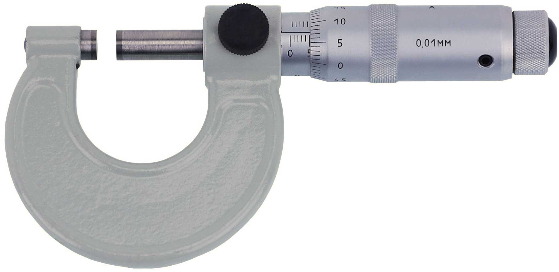
In this article I will describe the repair of standard smooth micrometers, as they are the most common. Additionally, I will describe the repair of lever and indicator micrometers, lever brackets. Let's talk separately about micrometers of highly specialized and large sizes - how to repair them? Micrometer repair and caliper repair have some common points, so it is wise to master both of these processes, starting with the repair of calipers, as they are simpler, but provide basic basic skills that are the same as micrometer repair.
Micrometer repair - step one
Work on repairing micrometers should be carried out in a specially equipped workshop in which the necessary requirements are met - lighting, the necessary tools and materials are available, exhaust (ventilation) is provided and the temperature regime is more or less observed. The employee must have all necessary materials. It is highly desirable that the workshop has a sink with cold and hot water.
A tool submitted for repair, regardless of the reason for which it was rejected, should be: disassembled and washed in gasoline (aviation grade or B-70, Galosh, white spirit). After this, the repairman inspects the disassembled parts of the micrometer for obvious defects - wear, corrosion, nicks, chips, deformation... If possible, these defects are eliminated. What is possible is replaced. Next, everything is lubricated and the micrometer is assembled. The technician evaluates the possibilities and repair options. The very process of disassembling and washing, removing corrosion and nicks, assembling, lubricating and setting to zero, in many cases already includes the repair itself - no more is needed.
An important point: before disassembling, and further, at the first stage, it is necessary to clearly identify obvious (visually visible) defects and assess the feasibility of repairs. Since today there are a variety of micrometers in circulation, from different manufacturers from many countries, the quality of their manufacture may vary. Sometimes manufacturers make a tool that is of little use for repair - simplifying the technology, reducing the cost... Of course, you can try to repair such a tool, but sometimes the wear there is too high, and all our efforts will not make this tool work for a noticeably long time.
Finishing of measuring surfaces
Although all micrometers now have carbide measuring surfaces, wear on the measuring surfaces is one of the most common reasons why they are rejected.
After assembly, implicit problems are diagnosed - for example, the development of a micrometer screw. For this purpose, gauge length gauges are used - the verification procedure is standard.
We check the ratchet with a dynamometer, and if there are deviations, we change the spring in the ratchet as a temporary measure - it can be slightly stretched.
We also check the micrometer screw for play. We remove the play along the axis with an external nut on the stem under the drum (collet clamp). The transverse play can be removed by removing the screw and placing a steel ball on the hole under the screw and hitting it with a hammer (of course, not too hard, otherwise the screw won’t go through at all).
We need to ensure not only the flatness of the measuring surfaces, but their mutual plane-parallelism, and this is complicated by the fact that one measuring surface rotates - which means we also need to ensure the perpendicularity of the plane to the axis of the micrometer screw. We must have laps - for each micrometer size, a set of four laps.
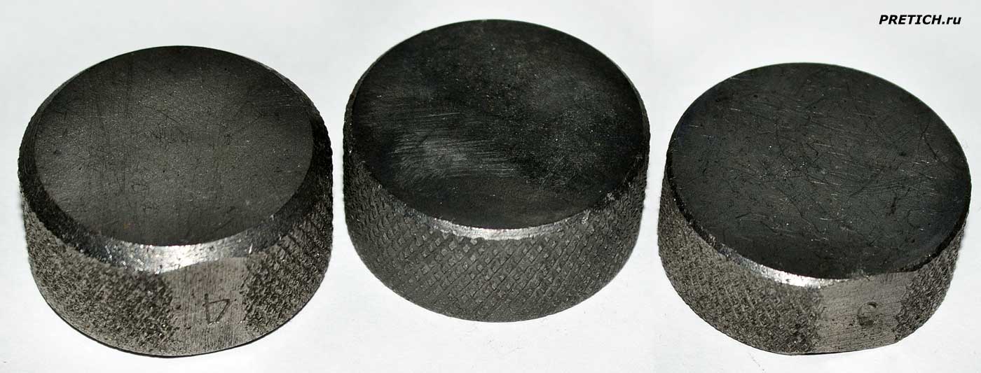
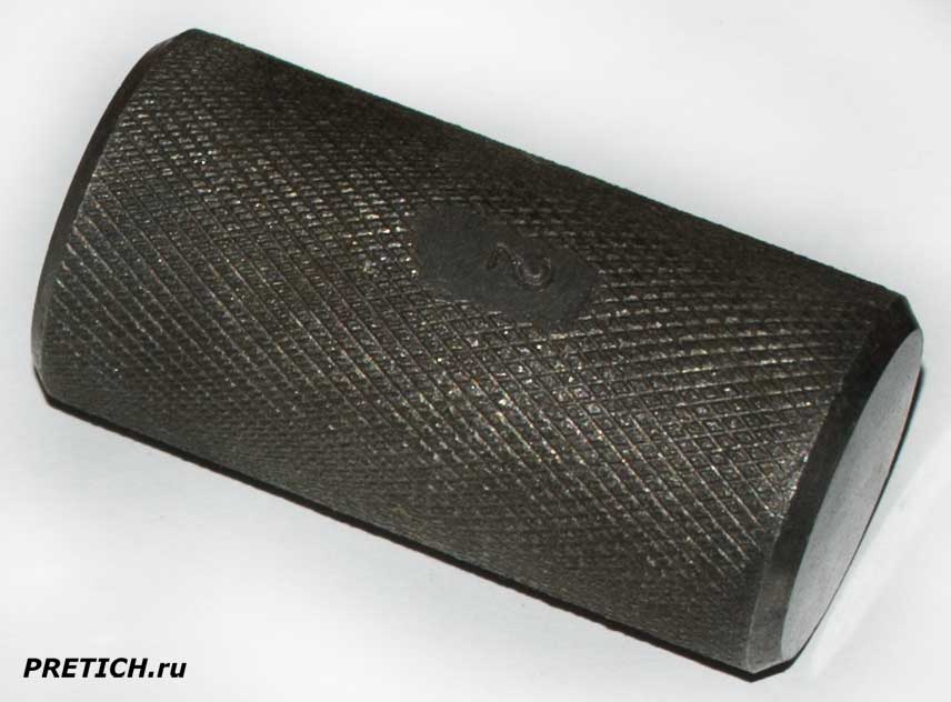
The laps are made of gray cast iron. For micrometers 0-25 mm, these will be four approximately such laps, with a diameter of 30 mm and a thickness of 15-20 mm. They should differ in thickness by 0.25 mm, i.e. each subsequent lap is 0.25 mm thicker than the previous one. For convenience, the edge of the lap should be knurled; on the side we make a small flat cut, where the number of the lap is stamped with a stamp. We adjust the lap on a cast iron finishing plate using white electrocorundum finishing powder - M10 or M20. Powder with kerosene is applied to the stove, mixed and evenly leveled. The planes must be parallel. The deviation from flatness and parallelism should not be higher than 0.1 mm (the more accurately you make the laps, the easier it will be to repair the micrometer). For control, we use an indicator stand with a table where a micator, microcator, opticator or 3ICHT type indicator is used.
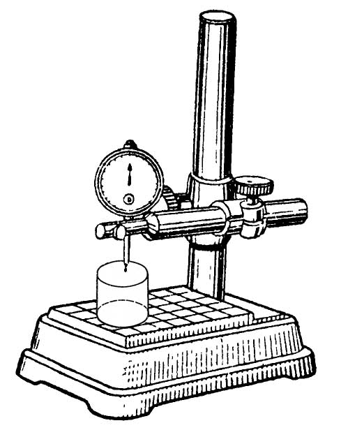
Lapping kits are made similarly for other micrometer sizes. But this finishing method no longer works effectively at sizes above 75-100 mm.
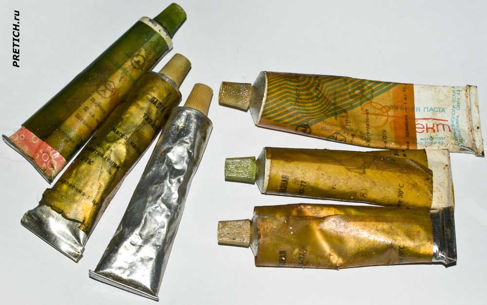
To refine the working surfaces of micrometers, green diamond paste with a grain size of 3.5-5-7 microns is used. These are AM 3, AM5 and AM 7. It is advisable to use the paste in tubes. You should not use large and small pastes on the same laps - you will not achieve a clean surface.
We apply a little diamond paste to the working surfaces of the lap and use another (next lap) to evenly distribute it over the surface - thus, we have two laps ready.
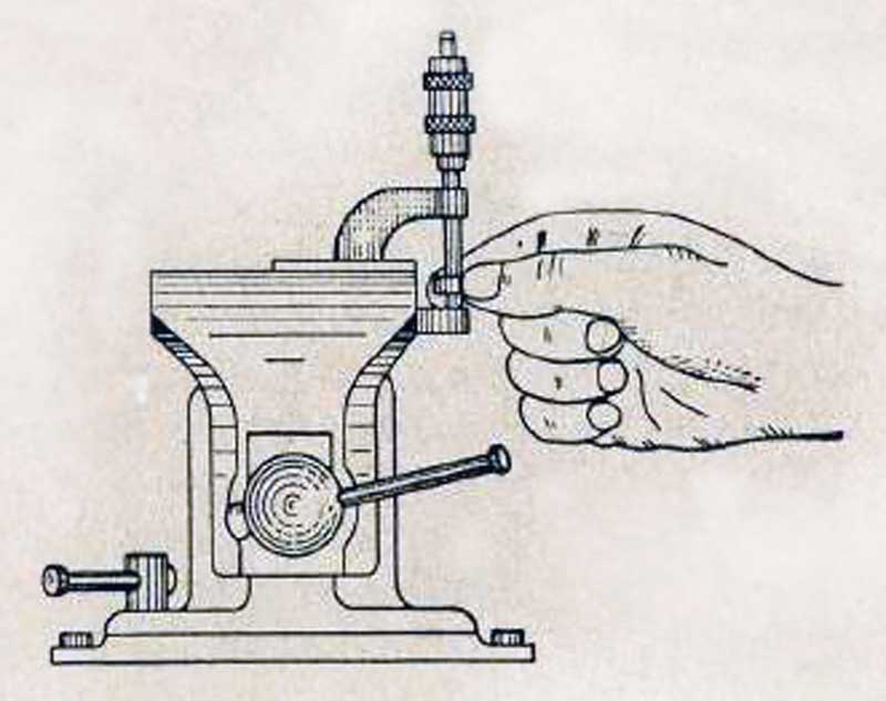
We clamp the micrometer in a vice with copper or brass jaws (or with such pads) - the lower part of the clamp, with the micrometer screw facing up. We insert the lap between the measuring heels and clamp it using a ratchet. The locking screw should be slightly tightened. We begin to move the lap with translational and reciprocal movements, which alternate with circular movements and constant rotation of the lap along the axis. Since we are finishing the hard alloy, the cast iron lap will be produced faster and our movements should be of such a nature that the production of the lap will be uniform across its entire working plane. During finishing, we tighten the screw through the ratchet.
Once the paste turns black and thickens, release it. Use a cloth to wipe the grinding surface and the heels of the micrometer. Regardless of the result, we repeat this operation with lap No. 2, and then with laps No. 3 and No. 4. Once this cycle is complete, we check the surfaces of the micrometer heels - they should be mirror-like. We check flatness and parallelism with a set of four glass plates, such as PM-15, PM-40, PM-65, PM-90.
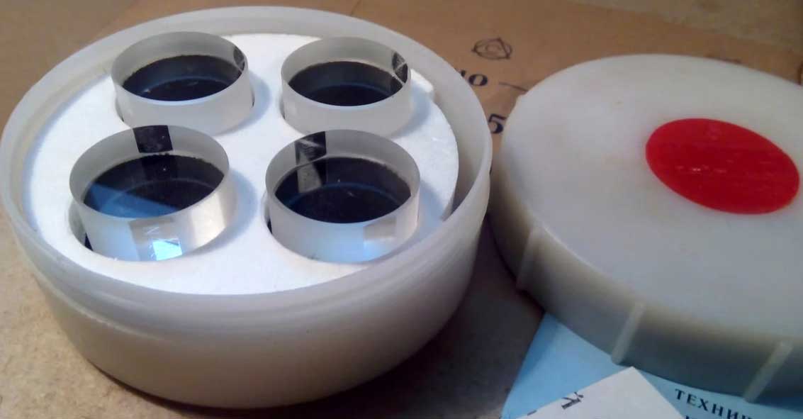
If wear remains on the heels of the micrometer, we carry out a second round of finishing with all four laps. If you have made the laps accurately and the micrometer has no play across the axis, you should get a positive result.
Typical errors in the process of fine-tuning micrometers:
- you are in a hurry, and friction heats up the lap and finishing surfaces - the temperature regime is disturbed;
- you clamp the lap tightly and make great efforts to move it;
- failure to ensure uniform use of the entire surface of the lap (leads to pits or bumps);
- incorrectly and tightly clamped micrometer clamp causes its deformation;
- there is no plane and parallelism - backlashes have not been eliminated, the bracket is deformed (this can also be caused by a jammed locking screw);
- your laps have worn out and lost their flatness, they need to be checked and corrected regularly;
- there is no mirror surface, which means you are using the wrong abrasive material.
Conclusion
Finishing micrometers is a fairly simple process; the necessary skills and experience are quickly developed. Of course, everything depends on your perseverance, perseverance (patience), and, of course, on the proper organization of the workplace and equipment with materials and tools.
As was said, we need a finishing plate, a stand with an indicator, a set of gauge blocks (class 2-3, or even decommissioned). As well as sets of glass plates - you can also use decommissioned ones, but they allow for rough inspection.
Lapping diamond pastes is an important point, necessary, without which success cannot be achieved. The hard alloy is diamond pastes or boron carbide, but the latter gives a matte surface. Here we talk about natural and synthetic abrasive materials.
In the second part we will look at the fine-tuning of lever and indicator micrometers, thickness gauges and other similar tools.
- The repair of micrometers is also discussed on our Forum in this thread.
- The original of this article in Russian is located here
Mikhail Dmitrienko, specially for PRETICH.ru
Almaty ©2023 |

